Apple IIe Implemented Battery Charge Controller
Introduction from 2001 when it was first built:
It was designed for a loud-music-junkie pal of mine who had so many amps hooked up to his battery / charger it kills both of them without something like this. The system monitors the discharge rate and when the voltage gets too low it turns on the charger until the voltage indicates the battery is fully charged.
The system uses a home brewed optical coupler to monitor the battery voltage and protect the Apple IIe and a Triac to turn the line voltage on and off to the charger. (I built the triac circuit to flash 'merry christmas' in morse code with the Christmas lights last December. It works with any 110V appliance up to 6amps, that's like 600+ watt, plenty.)
An easy software upgrade would be to use simple linear regression to predict when the battery will die at the current discharging rate. This enables it to see dimly into the future, so to speak, so it will turn on the charger before you even know it was needed =) For the same token, it will then be able to tell, at the current charging rate, how much longer until the charging will be done. (That one shouldn't be linear tho, but if we let the apple do it repeatedly at small time intervals, we'll still have a pretty good estimate.) Yeah, I could use all them fancy algorithms I learned in econometrics and multiple weirdo regressions to let it really crunch the future, maybe later.
I say easy because the code now already plots on the screen the charge/discharge rate. The computer just doesn't know it has access to the curve yet. (Right now it just plots it one point at a time.)
Oh yeah, this is one of the first projects of Pang Industries. Again, it is just a prototype, once I work out the requirements to replace the apple's job with a cheap microcontroller, we might see this on sale.
Here are some pics of the charge controller...
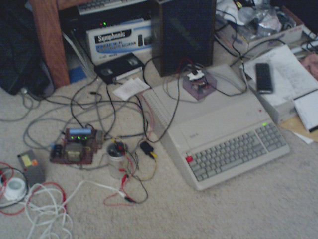
In the left with the green lights is the charger, which is hooked up to the control relay on top of the apple inside the plastic box in front of the speaker, that plugs into a 100V power outlet and the apple, so the apple can control if the charger gets turned on.

 the charger plugs into")

. When the battery is charged, the charger shuts off again, waiting for it to drain to a low nuff level...")


original image
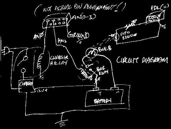
Circuit diagram and what the thing does (program flowchart)

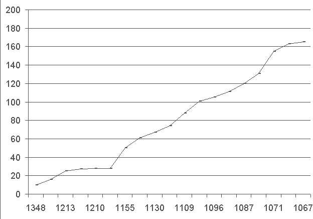
Vertical: resistance reported by Apple IIe PDL(0) port (0-255). Horizontal: Actual battery voltage as measured by multimeter during calibration. original image
(1348 = 13.48 Volt; 1067 = 10.67 Volt, etc)
A concern was the way voltages were taken by the computer, I didn't use a multimeter or anything, just LEDs, but the way the apple reads the resistance and the actual voltage was pretty linear in the range we are interested, so it's okay.
			10 HOME

			20 HGR

			30 IF PDL(0) < 250 THEN GOTO 100

			40 GOTO 30


			100 HGR

			110 HCOLOR = 2

			120 HPLOT 0, 128 TO 279, 128

			130 HCOLOR = 3

			140 X = 0


			150 Y = PDL(0) /2

			160 HPLOT X, Y

			170 X = X + 0.5

			180 VTAB 23: HTAB 5

			190 PRINT (255 - PDL(0)) * 0.05757; ' VOLTS',

			200 PRINT PDL(0)

			210 IF PDL(0) > 220 THEN GOTO 500

			220 IF PFL(0) < 30 THEN POKE 49240,0

			230 IF X > 279 THEN GOTO 10

			240 GOTO 150


			500 POKE 49241, 1

			510 VTAB 23: HTAB 5

			520 PRINT '---------CHARGER ON---------'

			530 GOTO 150
The program code the apple was running.
Views: 1413
Replies coming soon