Implementation of Cooler Crawler Throttle for model railroading
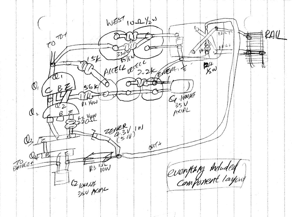
Component layout for soldering. Component not to scale. Modified to suit available parts.

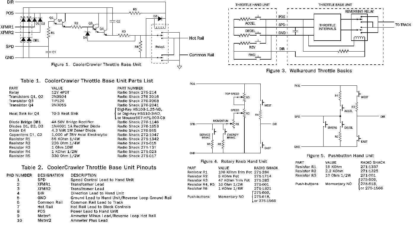
| Part | Value | Part number |
|---|---|---|
| Relay | 12V 4PDT | Radio Shack 275-214 |
| Transistors Q1, Q2 | 2N3904 | Radio Shack 276 2016 |
| Transistor Q3 | TIP120 | Radio Shack 275-2068 |
| Transistor Q4 | 2N3055 | Radio Shack 276-2041 |
| Heat Sink for Q4 | TO-3 Heat Sink | Digi-Key HS103-1.25-ND or HS110-3-ND, or Mouser567-HP1-TO3-CB |
| Diode Bridge DB1 | 4A 50V Bridge Rectifier | Radio Shack 276-1146 |
| Diodes D1, D2, D3 | 1N4001 1A Rectifier Diode | Radio Shack 276-1653 |
| Diode D4 | 4.3 Volt 1W Zener Diode | Radio Shack 276-565 |
| Capacitors C1, C2 | 1,000 uF 35V Axial Electrolytic | Radio Shack 272-1047 |
| Resistor R1 | 56 KOhm 1/4W | Radio Shack 271-1342 |
| Resistor R2 | 220 Ohm 1/4W | Radio Shack 271-015 |
| Resistor R3 | 1 Ohm 10W | Radio Shack 271-131 |
| Resistor R4 | 1 KOhm 1/2W | Radio Shack 271-023 |
| Resistor R5 | 330 Ohm 1/2W | Radio Shack 271-017 |
| Pad # | Designation | Description |
|---|---|---|
| 1 | SPD | Speed Control Lead to Hand Unit |
| 2 | XFMR1 | Transformer Lead |
| 3 | XFMR2 | Transformer Lead |
| 4 | Dir | Direction Lead to Hand Unit |
| 5 | GND | Ground Lead to Hand Unit/Reverse Loop Ground Rail |
| 6 | Common Rail | Common Rail Lead to Track |
| 7 | Hot Rail | Hot Rail Lead to Block Controls |
| 8 | POS | Power Lead to Hand Unit |
| 9 | Meter1 | Ammeter Minus Lead / Reverse Loop Hot Rail |
| 10 | Meter2 | Ammeter Plus Lead |
| Part | Value | Radio Shack |
|---|---|---|
| Resistor R1 | 1000 KOhm Trim pot | 271-284 |
| Resistor R2 | 5 KOhm Pot | 271-1714 |
| Resistor R3 | 47 KOhm Trim Pot | 271-283 |
| Resistor R4, R5 | 10 Ohm 1/2W | 271-001 |
| Resistor R6 | 1 KOhm 1/4W | 271-1321 |
| Push-buttons | Momentary NO | 271-609, 275-618, or 275-1566 |
| Part | Value | Radio Shack |
|---|---|---|
| Resistor R1 | 15 KOhm | 271-1337 |
| Resistor R2 | 2.2 KOhm | 271-1325 |
| Resistor R3 | 10 Ohm 1/2W | 271-001 |
| Push-buttons | Momentary NO | 275-609, 275-618, or 275-1566 |
Original design plans, schematic, and component list by Rich Weyand. The original image has been crudely butchered into the above image and four tables.
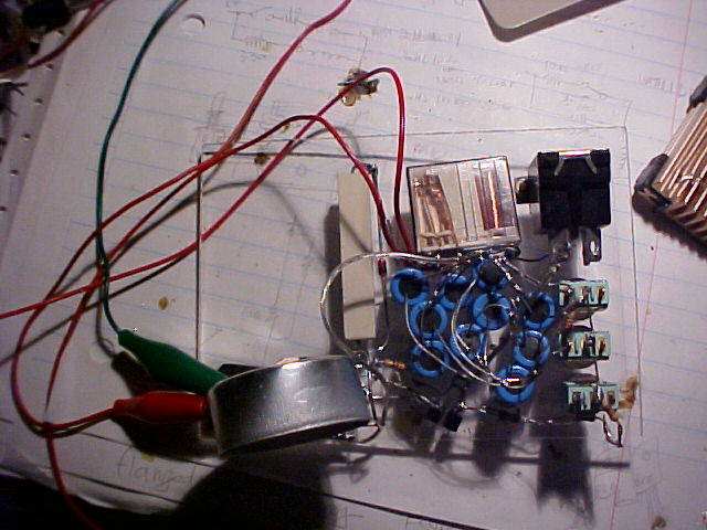
The magic is the way this circuit puts 'bumps' into the power supplied to the track. The idea is to jolt the motor at low rpm so it can crawl on the track.
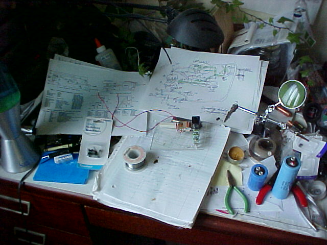
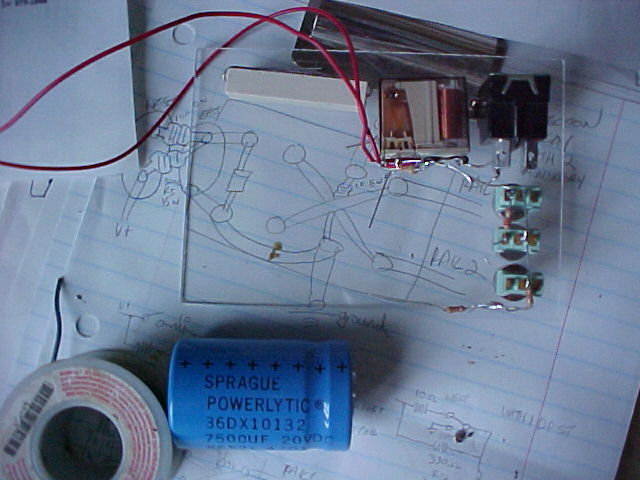
Must've spent like a week working out the layout on paper before I put the things together.
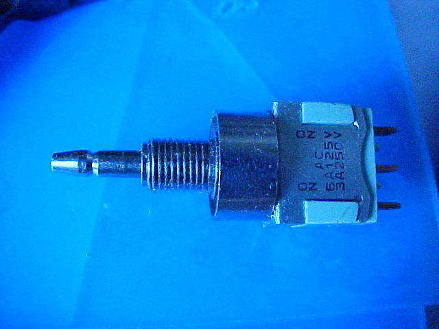
Those nice looking, nice feeling momentary push switches I got at Mike Quinn's just didn't work.
Didn't know until they were installed and had to remove hem and replace with Radio Shack ones.
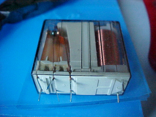
The next thing that sucked was the realy that does the reversing, they tended to stick ,return spring was not strong enough compared to the coil.
A bunch of bad component choices, like, not getting the right camp can be solved by ganging up a bunch of them together, right? That's what the text book said, but in real life its a nightmare. The heat sink is just a tea candle cup. Couple that with the bad switches and nothing works.
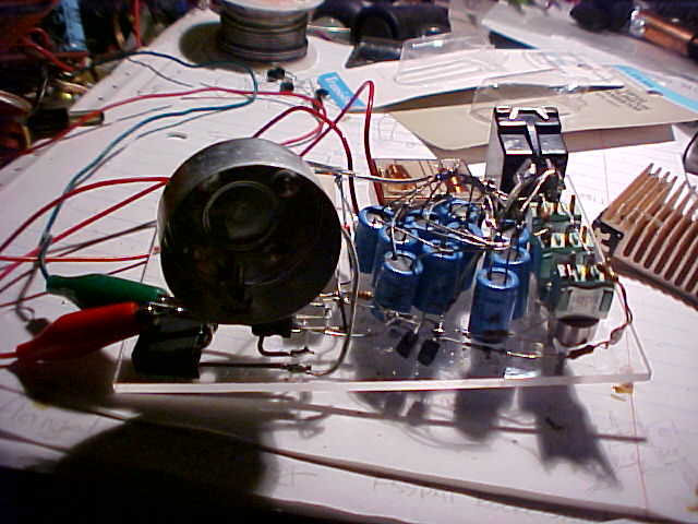
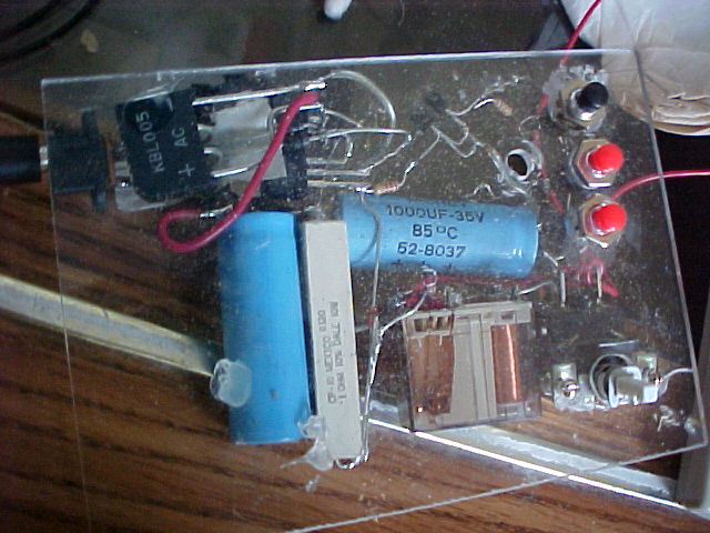
A few more bucks of investment later... a power supply that works.
Views: 1970
Replies coming soon